Q&A Forum
No, It isn't working like that. On gates there is 0-1V. I made few logs with oscilloscope. And it is behaving strange. Still i am thinking about thyristors. I have bought a little bit different model. In schematics SKCH, but I have SKBH which doesn't have one diode in internal diagram.
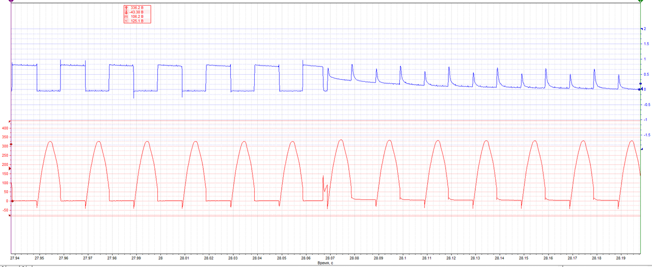
Here is what happens when I am quickly lowering voltage from yourdyno output 5V to 0V. This change in graph is when on SKPC pin 6 is voltage around 0,5V and lower.

This text is quoted from https://yourdyno.com/YourDynoHelp/eddy-current-brake-control/
"Make sure to select an SKCH that can take your max current and voltage. Also make sure that the bridge has a reverse diode. When the controller turns off power to the brake quickly, the current in the brake continues to flow for some time due to the stored magnetic energy. If there is no diode, the voltage increases until something breaks. The reverse diode solves the problem (make sure it can take the current too). There is also some filtering on the main supply."
I tried to ask earlier if you are having that reverse diode but my explaining was little bad. You were saying that you are using SKBH version of thyristors and its not containing reverse diode.
Pins 7 and pin 9 of the SEMIKRON SKPC200-240 TRIGGER MODULE aren't connected to the gates of the SEMIKRON SKCH 28/12 Controlled bridge rectifier ? Maybe i haven't understood what you have worded ??? Pins 7 and 9 are connected to the ANODES A1 and A2 respectively on the thyristers of the SKCH 28.
Pins 8 and 10 of the SEMIKRON SKPC200-240 TRIGGER MODULE are connected to the GATES G2 and G1 of the thyristers respectively on the SEMIKRON SKCH 28/12 Controlled bridge rectifier.
Thyristor pins 7 and 9 are thyristor gate pins that are connected to trigger module g1 and g2 pins.
What electrical block duagram are you getting your information from?
Cause I'm seeing it different my end ?
The one i have posted pin 8 is connected to thyristor GATE2 and pin 10 is connected to thyristor GATE1
Pins 7 and 9 are connected on the thyristor anodes sides.
 ?md5id=bdee0997d3fb6be8515a432051fe4e5c&new_width=1000&new_height=800&size=max&font_size=25&w=1466647023
from picture of semikron skch 28/12
Somehow this forum brokes link after ?
Ok that is more clearer your refering to the labelling on the semikron skch 28/12 gates number 7 and 9 as in this picture of semikron website PDF download datashete. Yes or No ?
Ok the two previous posts we were posting at the same time. Crossed paths. Just read it.
Where I'm refering to the labelling on the semikron SKPC200 phase angle module pinouts , that's where my confussion was! As to what you were say and i was saying. As can be seen here the pins 8 and 10 on the semikron SKPC200 are connected to the gates 1 and 2 in this picture posted here.
http://shop.semikron.com/en/Products-and-Shop/Product-Groups/Others/SKPC200-440.html
Here is what happens when I am quickly lowering voltage from yourdyno output 5V to 0V. This change in graph is when on SKPC pin 6 is voltage around 0,5V and lower.
But pin 6 on the SKPC200 Trigger
module is a input pin I/P from
yourdyno ? Interesting !

But the SKPC200 Trigger module
has optocouplers preventing
any damage to the YourDyno box??

Have you maybe damaged the yourdyno
blue box? Cause you didn't have a
diode protection on the
loads (telma retarders) ? Don't know?
You are making so much mess here. 😀
Pin6 is input pin on Semikron. These 2 graphs is from thyristor pin 7 and pin 3 or 4.
Your dyno can't be damaged and isn't damaged.
I think I have found my problem and it is 90% from this diode which isn't in my thyristor. I will change it and all should be fine.
LOL oopssssy Sorry! I said and asked if it had a diode in thyrister you used! way back and you said you had protection done. I better zip_it. All the best.
Using these thyristors: https://www.tme.eu/en/details/skbh28_06/single-phase-diode-thyristor-br-rectif/semikron/skbh-28-06/
Only going on by the link you posted for the thyrister you are using. In there dowload spec sheet it shows a block diagram with a diode on the output load wire. Enough said! Will not post anymore in this thread.
https://www.tme.eu/en/details/skbh28_06/single-phase-diode-thyristor-br-rectif/semikron/skbh-28-06/
you asked me about snubber/filter and yes I told that I put them on Semikron and retarder. you didn't say anything about diode.
