Q&A Forum
Hi,
I have an issue setting up the engine rpm on input rpm2.
When i connect an optocoupler to rpm2 i don't get a signal displayed. If i connect a led in series to the rpm2 input it is flashing.
If i connect the rpm sensor of the rollers on rpm2 i get a signal.
In the software i set rpm2 input to engine rpm and 1 pulse per evolution.
Do i have to do something else?
Kind regards,
Loic
Hi,
The Engine RPM channel is always equal to Roller RPM * gear ratio. This is what is used to calculate the power and torque, and to control the brake. This is a different channel from the RPM2 channel. RPM2 can be used to set the gear ratio (in case of a fixed gear box) or to plot the results vs the measured engine RPM.
You can also rename the RPM2 channel if you prefer a better name using a math channel (don't call it Engine RPM, as channel names need to be unique). You can also calculate the Torque vs this RPM channel with a math function. Power is correct irrespective of gear ratio.
Hi,
The big engine rpm gauge is working when the rollers are spinning and the gear ratio is set.
I want the rpm2 gauge to plot the measured engine rpm.
I connected the output of the optocoupler to rpm2. But i don't get a signal displayed to rpm2 gauge when the input is connected to a coil.
When i plug in the sensor of the rollers it gives a value to the rpm2 gauge.
The output of optocoupler is tested with a led and is working fine.
In the settings of the rpm setup; rpm 2 input function = engine rpm ; pulses per revolution = 1.
Do i have to configure something else to get it working?
From your description you connected it correctly and configured it correctly. There is nothing more you need to do.
Since the RPM2 input is working with the roller RPM sensor, it must be that the optocoupler/coil connection is somehow not working. If you have access to an oscilloscope then you can check if you get a 5V square wave on the RPM2 input. Without an oscilloscope it is difficult to check the signal, I cannot see how you did that with a LED.
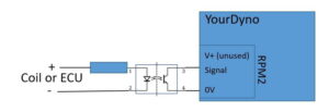
Where is the + of the optocoupler input connected?
For now i use an arduino to replicate an engine rpm of 1200rpm. It is connected to the input of the optocoupler.
On the output i connected a led to confirm that the optocoupler output is still working. The led is flashing.
If i switch the polarity on the input, the led on the output stops flashing.
With the arduino switched on i get a voltage of 4.77v between 0v and signal.
When i switch it of i get a voltage of 5v between 0v and signal.
I will check with an oscilloscope if i have a square wave of 5v.
I had the same problem using a basic optocoupler. I then bought the Sparkfun type and it works perfectly 🙂
The issue of the engine rpm is solved. I checked the output signal of the optocoupler with an oscilloscope. It gave a square wave between 1.4v and 5v.
With the sparkfun optocoupler it is a square wave between 0v and 5v.