Brake dynos
Brake/absorber dynos works by braking the engine and measuring the force (torque) it takes to brake it over the RPM range. Just leave the engine at wide open throttle and go through the RPM range by adjusting the braking force.
YourDyno can acquire the data during a run and supports both manual and automatic brake control.
The main challenge is the brake itself. The setup is quite simple once you have the brake. All you need on the instrumentation side for any of these brake dynos is included in YourDyno’s instrumentation kit.
Eddy current brakes
The Eddy Current brake is a popular professional brake and also more and more used by hobby racers with a bit of a budget. Eddy brakes is the most popular brake among YourDyno users. It is easy to use, does not get worn out, there are no messy water or oil and is easy to control accurately. If you can afford it, Eddy brakes is the way to go! his is unless you will test engines directly on the crank shaft, in which case Water brakes is a good option, see later.
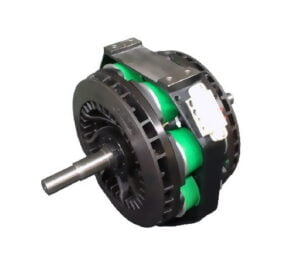
An Eddy Current brake
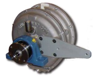
The more current you run through it, the more it brakes. These brakes are very good, but unfortunately a bit expensive (~$1500-$2000 and up for a new unit). You may be able to find a usable brake at salvage yards for buses and large trucks, as some have magnetic retarders, often by Telma. The braking force can be very accurately controlled with Eddy Current brakes. They are normally controlled directly by the dyno software, but can also be adjusted manually with a suitable power supply. See the page about Automatic Brake Control for a typical automatic brake setup with YourDyno.

This is gold! Look for Telma retarders at salvage yards
As with the other brakes, the Eddy Current retarder needs to be mounted such that the load cell prevents the retarder from rotating around its axis. You need two pillow bearings, one on each side of the brake.
Water brakes
A water brake
A popular alternative to eddy brakes is the water brake, in particular for those testing engines at the crank. The braking is controlled by adjusting the water flow, which can be done manually or electronically. More water in the brake = more braking. Note that the braking force is not determined directly by the valve opening, it is the fill level that determines the braking force. Water brakes are typically light and have the benefit that the heat generated is only heating up the water, which you can have in a very large container or cool down at low cost, so long runs and very high horsepower can be sustained. They have a unique property in that they can tolerate very high RPMs, so they can be connected directly to the engine crankshaft.
Water brakes can be a bit tricky to control and the setup can be challenging. The water pressure needs to be very constant and quite high (~3-5 bar). For high horsepower setups, water pumps of 4-6kW is normal! The valve also has some special requirements. Ideally we want a linear response, i.e. 50% brake input should produce twice the flow as 25% input. If you use a normal ball valve, this will not work, since a ball valve (and many other valves) have a very abrupt start and nothing much happens after the valve being half opened. The valve is controlled either by a stepper motor or a powerful servo.
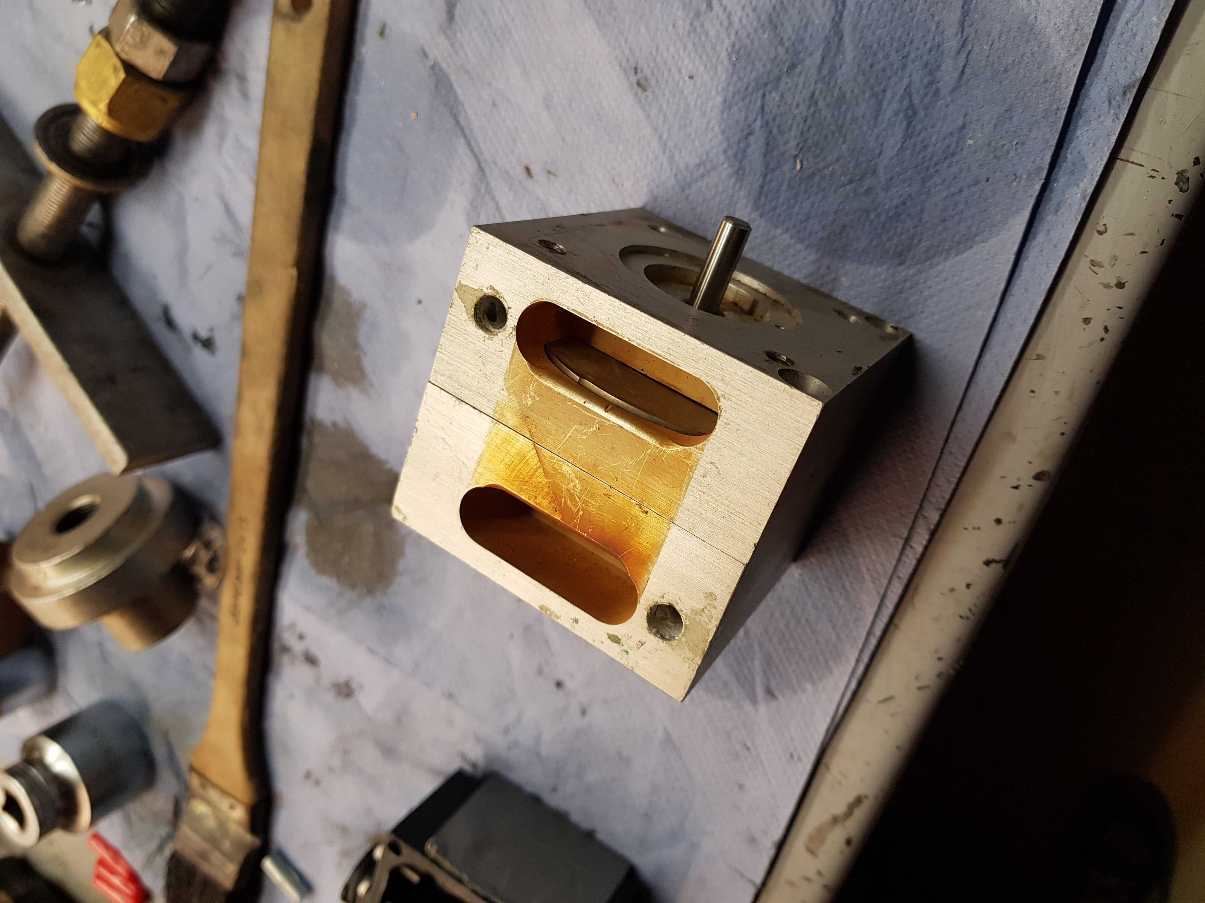

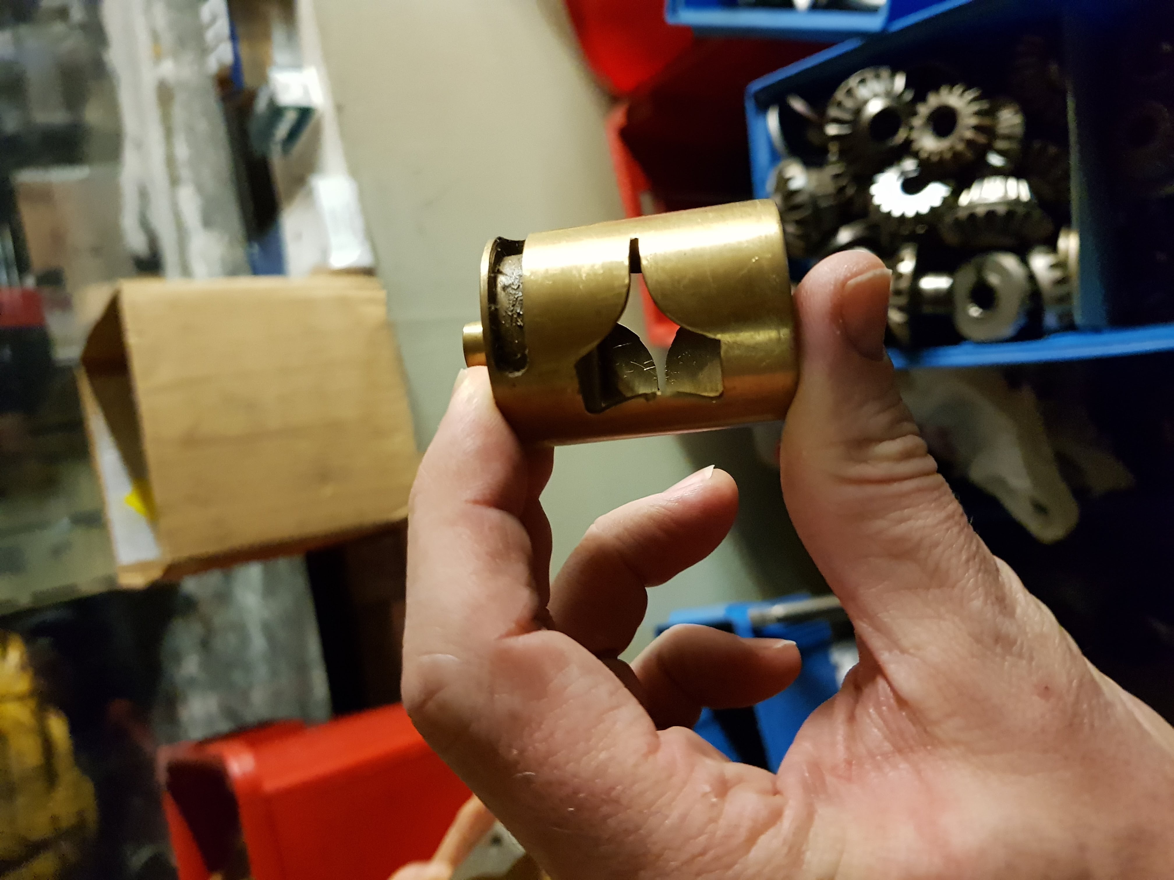
Here are two examples of water brake valves. Notice the very small water passage for low valve openings.
Other lower cost alternatives
There are several quite straight forward choices for a mechanically inclined person to choose from. They are typically not as versatile as the Eddy brake and Water brake alternatives when it comes to exact brake control.
One of my favorite solutions for a very low cost home dyno is the hydraulic brake. All you need is a hydraulic pump and an adjustable valve plus associated plumbing/tank. Hydraulic dynos can be difficult to control with PID controllers, but respond well to the “Brake sweep” brake mode (high to low RPM). Brake sweep gives a standard power graph vs RPM. Below you see an example of a hydraulic brake running an earlier version of YourDyno.
A simple and effective hydraulic brake dyno used up to about 85hp
See it in action here.
Here is what you need:
-
- High Pressure Hydraulic Gear or Vane Pump. Click here to learn how to choose the right hydraulic pump.
- A Flow control valve (example 1, example 2, example 3). Your valve should be made for fine adjustments.
- A high pressure hydraulic hose between your pump and your valve (example).
- A car wheel hub bearing (example) or something else that fits your setup to ensure the pump can rotate.
- A mechanical rig and a hydraulic tank with fittings and plumbings
- The YourDyno instrumentation kit
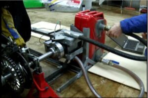
Note that the dyno in the video only has a (car hub) bearing on one side of the retarder. The axel bearing of the kart being tested serves as the second bearing. More details on this hydraulic brake here!
In the video above you see the the pump is kept from rotating by an arm towards the front of the car. It is connected to the load cell . You see the RPM sensor over the pump flange.
The total cost of the mechanical parts for this dyno was only around $200. It worked very well and was used up to about 85HP.
Dynos using car brakes are also possible for lower HP applications. Again accurate brake control can be difficult, but the Brake sweep mode from high to low RPM is typically possible.
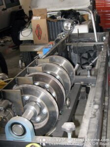
Brake dyno using car brakes
For smaller engines such as kart engines you can run one rotor/caliper setup, or for more powerful engines you can put many in parallel such as done here. Run the engine at max RPM and gradually push the brake pedal until engine RPM is below the interesting area. The brakes heat up pretty fast. Add fans and don’t run long runs if you have heat issues. In any case a run does not need to take more than 10 seconds or so. The calipers will need to be kept from rotating by the load cell. Pretty simple setup!
To test RC glow engines engines or electrical motors you can use another electrical motor loaded by resistors as the load. Here is an example:
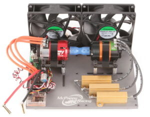 This setup uses fixed resistors, but can be improved by using an adjustable power resistor and a diode setup to load all phases of the engine with the same varying load.
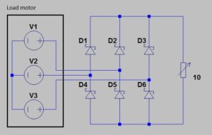
Here is the circuit that needs to be implemented. Adjust value and power rating for the power resistor depending on your setup.
All you need on the instrumentation side for any of these brake dynos is included in YourDyno’s instrumentation kit.
Inertia dynos
See this page for inertia dyno info.